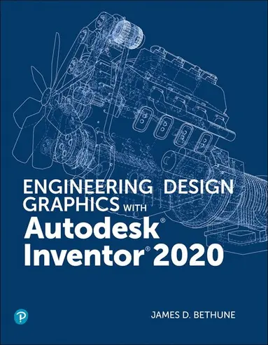

Engineering Design Graphics with Autodesk Inventor 2027
835 kr
Kommande. Bevaka för att få ett mejl när produkten kan beställas.
Beskrivning
Go beyond CAD basics with Autodesk Inventor 2027 training that connects design skills to real engineering applications.
Using a clear, step-by-step format, Engineering Design Graphics with Autodesk Inventor 2027 shows students how to create and document designs in Autodesk Inventor. Chapter test questions, sample problems, end-of-chapter projects, and additional exercises reinforce key concepts and give students hands-on practice. Going beyond typical CAD instruction, the book also includes exercises that challenge students to design simple mechanisms, helping connect software skills with practical engineering design and problem-solving. This book includes the following features:
- Updated for Autodesk Inventor 2027, with coverage aligned to the latest software features.
- Step-by-step instruction helps students work directly from the text to the screen and provides a useful reference during and after the course.
- Comprehensive coverage spans two-dimensional sketching, 3D models, assemblies, and detailed drawing generation.
- Chapter tests, sample problems, end-of-chapter projects, and additional exercises support self-assessment and hands-on practice.
- Mechanism-design exercises encourage students to apply Inventor skills to realistic engineering problems.
- ANSI and ISO standards are discussed where appropriate, introducing students to relevant techniques and national standards.
Produktinformation
- Utgivningsdatum:2027-03-08
- Mått:216 x 274 x 27 mm
- Vikt:1 618 g
- Format:Häftad
- Språk:Engelska
- Antal sidor:816
- Upplaga:1
- Förlag:Pearson Education
- ISBN:9780135571620
Utforska kategorier
Mer om författaren
James (Jim) Bethune taught drafting and Computer Aided-Design (CAD) for 39 years, twice winning the Outstanding Professor of the year award. He has a doctor's degree in education from Boston University and has written 21 books on drafting and CAD. While retired from full-time teaching, Jim continues to teach courses and write textbooks on CAD. An avid golfer, Jim lives in East Greenwich, Rhode Island.Samuel Weber is an AI and digital learning leader with over 17 years of experience designing and delivering technical training solutions across higher education and enterprise environments. Through Greer Consulting, he specializes in translating complex technical workflows into practical, real-world learning experiences.
Innehållsförteckning
- Chapter 1: Get Started 1Chapter Objectives 1Introduction 1Creating a First Sketch 4The Undo Tool 9Creating a Solid Model 9Sample Problem SP1-1 12Sample Problem SP1-2 Angular Shapes 17 Chapter 2: Two-Dimensional Sketching 25Chapter Objectives 25Introduction 25The Sketch Panel 25Circle 31Arc 34Spline 36Ellipse 38Point 41Rectangle 41Fillet 43Chamfer 44Polygon 45Text 47Geometry Text 48Dimension 49Constraints 49Pattern — Rectangular 51Pattern — Circular 53Pattern — Mirror 54Move 54Copy 55Rotate 56Trim 57Extend 58Offset 59Editing a Sketch 60Sample Problem SP2-1 62 Chapter 3: 3D Models 77Chapter Objectives 77Introduction 77Extrude 77Taper 79ViewCube 81Revolve 85Holes 85Fillet 87Full Round Fillet 88Face Fillet 89Creating a Variable Fillet 90Chamfer 90Face Draft 92Shell 93Split 95Mirror 97Rectangular Pattern 97Circular Pattern 98Sketch Planes 99Editing a 3D Model 105Default Planes and Axes 108Work Planes 109Sample Problem SP3-1 110Angled Work Planes 112Offset Work Planes 114Work Points 116Ribs (Webs) 119Loft 121Sweep 124Coil 126Model Material 127 Chapter 4: Orthographic Views 147Chapter Objectives 147Introduction 147Fundamentals of Orthographic Views 148Orthographic Views with Inventor 154Isometric Views 160Section Views 161Offset Section Views 164Aligned Section Views 165Detail Views 166Break Views 167Auxiliary Views 168ASME Y14.3-2003 171 Chapter 5: Assembly Drawing 203Chapter Objectives 203Introduction 203Bottom-Up and Top-Down Assemblies 203Starting an Assembly Drawing 204Degrees of Freedom 206Free Move and Free Rotate Tools 208Constrain 209Presentation Drawings 216Animation 219Isometric Drawings 220Assembly Numbers 223Parts List 225Title Block 228Subassemblies 230Drawing Sheets 234Other Types of Drawing Blocks 237Top-Down Assemblies 241Editing a Part Within an Assembly Drawing 261Patterning Components 264Mirroring Components 265Copying Components 266 Chapter 6: Threads and Fasteners 291Chapter Objectives 291Introduction 291Thread Terminology 292Thread Callouts—Metric Units 292Thread Callouts—ANSI Unified Screw Threads 293Thread Representations 294Internal Threads 295Threaded Blind Holes 296Creating Threaded Holes Using the Hole Tool 299Standard Fasteners 301Sizing a Threaded Hole to Accept a Screw 303Screws and Nuts 307Types of Threaded Fasteners 310Flat-Head Screws—Countersunk Holes 312Counterbores 314Drawing Fasteners Not Included in the Content Center 318Sample Problem SP6-1 319Washers 323Setscrews 326Rivets 328Sample Problem SP6-2 329 Chapter 7: Dimensioning a Drawing 367Chapter Objectives 367Introduction 367Terminology and Conventions—ANSI 368Creating Drawing Dimensions 370Drawing Scale 378Units 379Aligned Dimensions 381Radius and Diameter Dimensions 383Dimensioning Holes 385Sample Problem SP7-1 386Dimensioning Counterbored, Countersunk Holes 390Angular Dimensions 391Ordinate Dimensions 393Baseline Dimensions 396Hole Tables 398Locating Dimensions 399Fillets and Rounds 401Rounded Shapes—Internal 401Rounded Shapes—External 402Irregular Surfaces 402Polar Dimensions 403Chamfers 404Knurling 405Keys and Keyseats 405Symbols and Abbreviations 406Symmetrical and Centerline Symbols 407Dimensioning to a Point 407Dimensioning Section Views 408Dimensioning Orthographic Views 4083D Dimensions 409Sample Problem SP7-2 410Sample Problem SP7-3 412 Chapter 8: Tolerancing 433Chapter Objectives 433Introduction 433Direct Tolerance Methods 433Tolerance Expressions 435Understanding Plus and Minus Tolerances 435Creating Plus and Minus Tolerances 436Limit Tolerances 440Angular Tolerances 441Standard Tolerances 443Double Dimensioning 444Chain Dimensions and Baseline Dimensions 445Tolerance Studies 447Rectangular Dimensions 448Hole Locations 448Choosing a Shaft for a Toleranced Hole 449Sample Problem SP8-1 451Sample Problem SP8-2 452Nominal Sizes 452Standard Fits (Metric Values) 453Hole and Shaft Basis 455Visual Presentations of the Hole and Shaft Tolerances 456Standard Fits (Inch Values) 457Preferred and Standard Sizes 457Surface Finishes 458Surface Control Symbols 460Geometric Tolerances 470Tolerances of Form 470Straightness 471Straightness (RFS and MMC) 472Circularity 474Cylindricity 475Geometric Tolerances Using Inventor 476Tolerances of Orientation 483Datums 484Perpendicularity 486Parallelism 488Angularity 488Profiles 489Runouts 490Positional Tolerances 492Virtual Condition 494Floating Fasteners 494Sample Problem SP8-3 495Sample Problem SP8-4 496Fixed Fasteners 497Sample Problem SP8-5 498Design Problems 499 Chapter 9: Springs 543Chapter Objectives 543Introduction 543Compression Springs 543Extension Springs 550Torsion Springs 556Belleville Springs 559Springs in Assembly Drawings 561 Chapter 10: Shafts 585Chapter Objectives 585Introduction 585Uniform Shafts and Chamfers 586Shafts and Retaining Rings 590Shafts and Keys 594Square Keys 595Pratt and Whitney Keys 601Woodruff Keys 606Shafts with Splines 609Collars 615Drawing Shafts and Pins Using the ToolsUnder the Design Tab 623 Chapter 11: Bearings 647Chapter Objectives 647Introduction 647Plain Bearings 648Ball Bearings 653Thrust Bearings 657 Chapter 12: Gears 671Chapter Objectives 671Introduction 671Gear Terminology 672Gear Formulas 673Drawing Gears Using the Gear Tool 674Gear Hubs 675Gear Ratios 679Gear Trains 680Gears with Keyways 682Gear Assemblies 685Supports for Bevel Gears 697Worm Gears 699Supports for Worm Gears 701 Chapter 13: Sheet Metal Drawings 719Chapter Objectives 719Introduction 719Sheet Metal Drawings 719Flat Patterns 732Punch Tool 733 Chapter 14: Weldment Drawings 749Chapter Objectives 749Introduction 749Fillet Welds 749Weldments—Groove Welds 759Sample Problem SP14-1 760 Chapter 15: Cams 767Chapter Objectives 767Introduction 767Displacement Diagrams 768Drawing a Cam Using Inventor 769Sample Problem SP15-1 773Cams and Followers 775 Index 789 Chapter 16 and Appendix A are available online at peachpit.com/register
Du kanske också är intresserad av
Diskursanalysen 2: Institution Universität
Friedrich A. Kittler, Manfred Schneider, Samuel Weber
Häftad, 1990
415 kr
Diskursanalysen 2: Institution Universität
Samuel Weber, Manfred Schneider, Friedrich A. Kittler
452 kr